Blogs

First meeting with BLE (Bluetooth low energy)

Introduction

This post will mostly consist of pictures, since I did not have too much time to play with the device itself. Hopefully I will find more spare time to write more detailed article about this particular development kit. Some time ago I have spotted really cheap Bluetooth low energy development kit from TI. It was only $25USD, shipping included! I ordered one immediately. More than a month later I have received a ridiculously big package from Netherlands. There was a small box of CC2541 SensorTag Development kit and a lot of air-filled bags :)

CC2541 SensorTag in the boxCC2541 SensorTag in the package

Raspberry Pi: First Steps

Raspberry Pi

Introduction

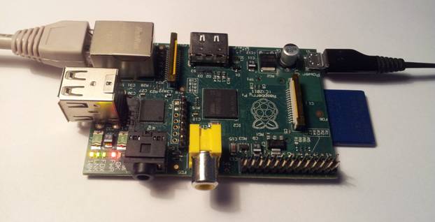
Raspberry Pi is a popular single board computer with 700MHz ARM11 microprocessor, Broadcom VideoCore IV GPU, 256 or 512 MB of RAM and uses SD card as its storage for operating system and user data/files. This single-board computer has a stereo audio output, easily accessible RCA Video and HDMI outputs, 10/100 Mb/s LAN connector and 1 or 2 USB ports. These peripheral makes Raspberry Pi interesting for all people who have knowledge of Linux operating system. Additional GPIO connector makes it interesting for electronics engineers as well.  This single-board computer can be used in many applications - from home media center to the "brain" of a complicated robot.

From electronics engineering point of view, computing power and available LAN, USB, GPIO connectors of the Raspberry Pi are the main interests. For this reason, it is necessary to remove the need of extra keyboard and TV/monitor to operate and control this single-board computer. This article describes how to set up a Raspberry Pi so it would be possible to set up, use and hack it without external keyboard or screen. First we will discuss the necessary software, required steps to setup and boot Linux, as well as setting up a network connection. Raspberry Pi will be prepared for making further changes using SSH terminal client from a PC.

Reverse engineering a chinese segway: working principles of motor control

After dismantling chinese copy of segway I wanted to check how the controller is made.   After a couple of hours of work with multimeter, pen, a sheet of paper and Kicad I came up with a block diagram and schematic of motor controller. This motor controller is made in a cheap and a very simple way. Reverse engineering and analysing this unit is a very good way to learn the basics of motor control. Here are some pictures of dismantled motor controller:

DC motor controller without coverDC motor controller main boardDC motor controller main boardDC motor controller main board, bottom sideVoltage delay circuit

Segway in a Chinese way

 
Some time ago I bought a chinese copy of segway. From far away you could think it is a real segway, but when you come closer you see that this is only an optical illusion :) It seems Chinese people don't like to bother themselves by using accelerometers, gyroscopes or even microcontrollers (we'll come to it later). The best way to make this "segway" look and work like a real segway is to put two extra small wheels and hide them under the plastic cover. Because this is the first time I see this kind of thing and it was not working properly (batteries were dead) I had to take it apart. I didn't have camera with me, so all pictures are taken with a cellphone. Sorry for bad quality.
 
Under the hood
Rear view of Chinese segwayBase of Chinese Segway

Pages

Subscribe to RSS - blogs