Connection of Elduino CAN128 V1.0

This is a short description of the connections on Elduino CAN128 board.
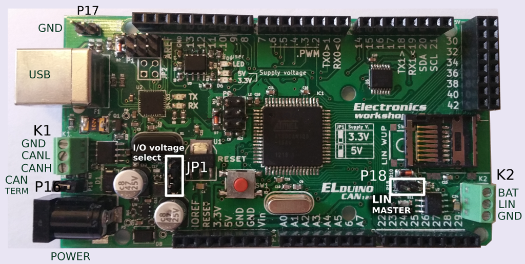
Elduino CAN128 V1,0 connections


CAN bus
K1 – Two wire CAN bus connector. 
P16 – Jumper connects the terminating resistor (120R) to the CAN bus. Do not mount it when you connect it to the car.
 
 LIN bus
K2 – LIN bus connector. Pin BAT has to be connected to +12V from external power supply.
P18 – LIN bus master/slave selection. If mounted, Elduino board is master on the LIN bus. If taken off – it is a slave.
 
For debugging
P17 – two additional GROUND pins. For easy voltage/signal measurement with oscilloscope, multimeter or logic analyzer.
JP1 – selects the microcontroller and board I/O voltage levels (3,3V or 5V). Please allways set it to 5V (two lower pins are shorted).

Komentarai

Comment: 
Hi Vaidas, is it possible to change voltage level to 3.3v? why i'm asking, you mentioned that it should set to always to 5v.   
By Farman (nepatvirtina)

Comment: 
It is possible to change voltage level to 3,3V, however this puts microcontroller outside its specifications. The microcontroller is clocked at 16MHZ and according to the datasheet microcontroller should be powered from 5V with this clock frequency. I did not have problems running the microcontroller at 3,3V and 16MHZ, but it is not a reliable and recommended solution. Also, when running microcontroller at 3,3V you have to make sure that you do not connect 5V level signals to it.
By gassrini

Komentuoti

Filtered HTML

  • Web puslapių adresai ir el. pašto adresai automatiškai tampa nuorodomis.
  • Leidžiamos HTML žymės: <a> <em> <strong> <cite> <blockquote> <code> <ul> <ol> <li> <dl> <dt> <dd>
  • Linijos ir paragrafai atskiriami automatiškai

Plain text

  • HTML žymės neleidžiamos.
  • Web puslapių adresai ir el. pašto adresai automatiškai tampa nuorodomis.
  • Linijos ir paragrafai atskiriami automatiškai
CAPTCHA
Šiuo klausimu norima išsiaiškinti ar jūs ne robotas
Please prove you are not a robot:
Question text provided by textcaptcha.com