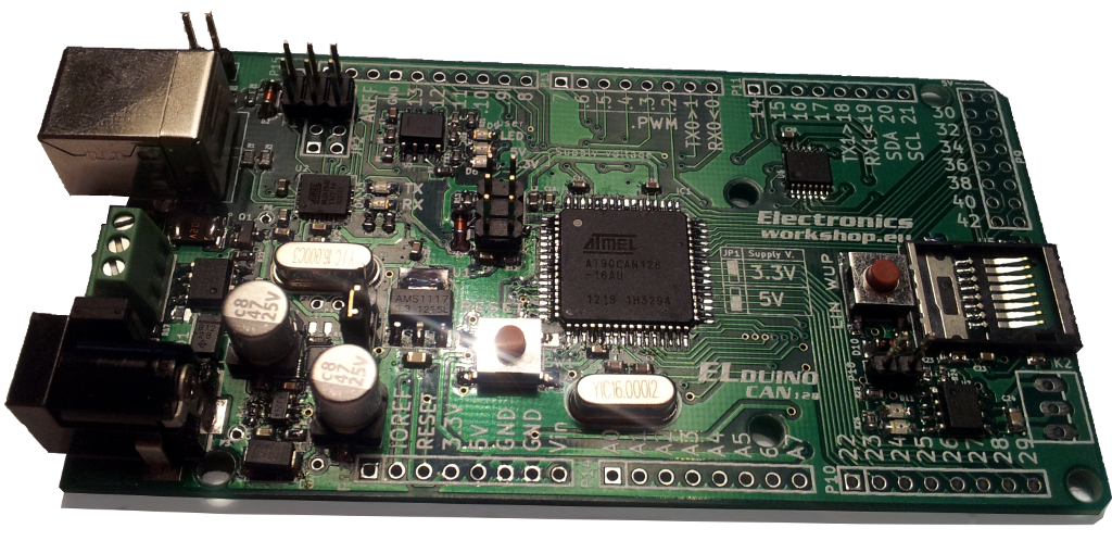
Elduino CAN128 - prototype assembly and testing in process
As mentioned in the previous post, I am working on the new board. When designing hardware it is usually very hard to define final requirements of the design. Quite often you have to add something you have never tested before in a real life. Also, it is very rare to make things work from the first time, mostly there is allways something to tweak after you have your device built.

Several weeks ago I have ordered small quantity of prototype PCBs and parts just enough to build three boards. In development stage you should allways have at least one extra device made. This way you might have a little bit higher expences, but you will save a lot of time fixing the failed devices ( this happens when you least expect it! ). When making order for parts I have missed the female pin headers. I had only a few left in my inventory, thus I could not fully assemble the boards. I have ordered new parts and waiting for them to arrive. It is good that this waiting period does not completely stop the board tests.
Assembly process went smoothly, all footprints of the parts were correct which came as a nice surprise ( usually the first spin of the board has some minor mistakes ). It was a little bit harder to solder the ATMEGA16U2 microcontroller. It gets a little bit tricky when you solder such components with a regular soldering iron.
First steps of the test
After the assembly comes very interesting part - testing. At the beginning only power supply section of the board was assembled and tested. This prevents other components from being damaged in case of power supply design mistakes. Power supply test gave positive results, but showed that there are some stability issues with the DC/DC converter. Further investigations showed that it is easily fixable by tweaking a couple of components.
The next test - checking if microcontrollers respond to the programmer. This test have passed with no problems. Of course, if you don't have any, you make them yourself. When programming the fuse bits for the main microcontroller in stead of external crystal resonator I have chosen other option, most likely the external oscillator. This made the chip invisible to programmer. In order to solve this, I had to use external signal generator, connect it to one of the crystal resonator's pins and change the microcontroller's fuse bits to the right values.
Testing boards peripherals and modifying the bootloader
In order to verify functionality of the peripherals, test firmware had to be written. First of all I have just launched the AVR Studio and wrote a simple code to toggle the whole PORTB of the main microcontroller every second. This showed that the microcontroller is functional, the user LED part was working properly. Since it is easier to work with the board without external programmer, Arduino compatible bootloader had to be adapted to the board.
First of all, I have flashed the USB-UART bridge with the hexfile found on Arduino website. USB-UART bridge worked like charm. Now that I had connectivity between PC and main microcontroller, I had to modify the Arduino's bootloader in order to support the AT90CAN128 microcontroller. Since the bootloader's code is very well written I managed to add support for the AT90CAN128 microcontroller in half an hour!
After having a working bootloader I started working on adding new board support to Arduino IDE. After a couple of hours I managed to add support and test all digital input/output pins, as well as analog input and PWM outputs. Both UART/Serial connections works fine. SD card example sketches showed me that both microSD card part and SPI connectivity works. Writing a quick library for internal microcontroller's CAN peripheral showed good results as well - now I can both send and receive packets trough CAN bus.
You can find the modified bootloader source code, hex files and schematic of the board below:
During testing and assembly processes I have faced many minor problems I had to fix. Those will be covered in the future posts.
UPDATE:
In order for Elduino CAN128 to work with Arduino IDE, you will need:
1) add following lines to boards.txt file:
##############################################################
can128.name=Eduino CAN128 (AT90CAN128)
can128.upload.protocol=wiring
can128.upload.maximum_size=126976
can128.upload.speed=115200
can128.bootloader.low_fuses=0xFF
can128.bootloader.high_fuses=0x9A
can128.bootloader.extended_fuses=0xF5
can128.bootloader.path=stk500v2
can128.bootloader.file=stk500boot_v2_can128.hex
can128.bootloader.unlock_bits=0x3F
can128.bootloader.lock_bits=0x0F
can128.build.mcu=at90can128
can128.build.f_cpu=16000000L
can128.build.core=elduino
can128.build.variant=can
2) Extract the zip file contents to <Arduino dir>\hardware\arduino\cores\elduino
Elduino support package for Arduino IDE (07102014)
3) Choose the Elduino board from Arduino IDE->Tools->Boards->Eduino CAN128 (AT90CAN128)
4) Choose the right COM port
5) Try the example above:

Komentarai
Komentuoti