Segway in a Chinese way
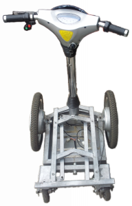
Some time ago I bought a chinese copy of segway. From far away you could think it is a real segway, but when you come closer you see that this is only an optical illusion :) It seems Chinese people don't like to bother themselves by using accelerometers, gyroscopes or even microcontrollers (we'll come to it later). The best way to make this "segway" look and work like a real segway is to put two extra small wheels and hide them under the plastic cover. Because this is the first time I see this kind of thing and it was not working properly (batteries were dead) I had to take it apart. I didn't have camera with me, so all pictures are taken with a cellphone. Sorry for bad quality.
Under the hood


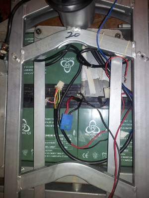
After taking off the plastic cover it is possible to see everything that is inside. Frame is made of metal. There are three 17Ah lead acid batteries, fixed in place with double sided duct tape. Motor controller is taken out in this picture. It was fixed to the bottom of the battery box with double sided duct tape. There is a 30A fuse in a fuse socket between two batteries. Three battery terminals are very close to each other, the gap between them was filled with hot glue to prevent short circuit. I only had to take off the cover to get a little bit surprised about the quality and attitude of work.
Steering and suspension

Steering and suspension (if you can call it like that) is made in a simple way. Turning handle bar turns both rear wheels to the same side. This makes this vehicle hard to control for a regular person who is not used to rear wheels steering system. Even though center of the mass of this vehicle alone is close to the ground, when an adult stands on it, center of the mass goes up drastically. Distances between wheels are very small, so it easy to fall down from this vehicle making turns on a higher speeds(I almost fell down couple of times).
There is no real suspension in this vehicle, but rear wheels try to adjust to the surface. Both rear wheels are mounted on the same square metal pipe which is fixed to the chasis of the vehicle with a freely moving junction in the center. This lets rear wheels move in a vertical direction as you can see from the picture above (right rear wheel is in a hole). Even though rear wheels tries to adjust to the surface, this vehicle makes a lot of sound when driving on an uneven surface.
Brakes

This vehicle has very inefficient brakes. There is only one disc brake and it is mounted on a right rear wheel. It seems, that bake disc is made of a regular metal. After driving this vehicle for a kilometer or a little bit more it is easy to see that tire of rear wheel is worn a lot more than braking pads.
Motor controller


Motor controller is built in an extruded aluminum case. Covers from the sides with mounting holes are probably made of steel. Very interesting thing - instead of making a hole with rubber tube for taking the wires out there was one more invention. Top cover is made of two pieces of extruded aluminium profile. This could be not a big disaster if this unit were build somewhere on the stationary wall with no movement, but this is a vehicle.. Using it everything moves, causing wires to rub to sharp edges of aluminium profile. I bought a completely new unit, I did not drive it at all and it was already possible to see that some of the wires are slightly cut already.


Motor controller is made of three parts - main board with power transistors and control circuitry, power relay and motor reverse control relay block. Of course, only one the main board was put into the rails of case, other board and power relay was just fixed to the bottom of the case with double sided duct tape.
Power relay is a regular Chinese brand relay with one pair of contacts and 36v coil. It connects output switches with a positive battery terminal. Coil is activated by turning the key to either on or reverse positions.
Motor reverse relay block consists two relays with 36v coils. Together with relays there is a small circuit which prevents from changing moving direction while vehicle moves. This is probably done by sensing motor voltage. If you change driving direction while driving it does not have any effect until you stop completely. Then it switches relays to drive to the other direction.
Main board is very simple. Main element is LM339D quad comparator. All four comparators are used.
First comparator is responsible for generating triangular signal. Second comparator makes PWM by comparing generated triangular signal and motor speed control voltage. Third comparator measures voltage across the piece of wire connected between power transistors source and ground. If voltage exceeds preset limit, comparator pulls down the speed control voltage input of second comparator. Fourth comparator measures battery voltage and pulls down the speed control voltage input when battery voltage is lower than the preset value. Motor speed control voltage is taken from throttle pedal output through a small circuit that delays voltage rise. This small circuits makes an impression that this vehicle is very slow, because speed control voltage reaches maximum in about 10 seconds. Every time you release the pedal, you need to wait 10 seconds to reach the full available power.
Standard current limit was set to 30A, under-voltage protection was set to approximately 31V. When either current reaches maximum or voltage falls down to preset value, motors make fairly quite strong extra sound. Even though the controller has overcurrent protection, I managed to blow it just in less than 20 seconds by stopping close to a small (~3cm high) step and trying to climb it by applying full throttle.
Hub motors

Vehicle is pulled by two brushed DC motors populated inside the wheels. Motors are connected in parallel. Short testing of those motors showed that taking 750W peaks of electric power from the battery does not generate too much excessive heat in a wheel's coil. Wheel bodies were barely warm after constant acceleration and deceleration for 5 minutes on a warm summer day (I think outside temperature during test was around 25C).
Tests done and further plans
After burning the power transistors and freewheeling diode of controller I changed them to mosfets that I had in my drawers (IRF3805). Instead of freewheeling diode I put the same mosfet (actually PCB was designed for mounting a mosfet there, shorting gate and source pins to prevent it from opening, so only body diode would be used). Speed signal delay circuit was removed to make it easier to test full power of the motor. Instead of dead lead acid batteries 12 pieces of 40Ah LiFePO4 Thundersky batteries were connected to get a lower voltage sag.
Trying to test possibilities of this vehicle with 30A current limit and LiFePo4 batteries was very hard. It was possible to test if the motors are getting hot after rapid speed up - slow down cycles, but top speed is still a mistery. It is possible to drive this vehicle with speeds up to 10km/h, after that driving it is the same as playing russian roulette :)
I would say that this copy of segway is good to drive at low speeds on an even surface, just to have some fun. In real life conditions it is useless. However, it is a very good toy if you want to learn basics of electric vehicles, power electronics and motor control. It was worth buying this "segway" just because of the wheels are seem to be made in a better way than the whole vehicle. I am planing to make a new chasis for my own electric vehicle and use those wheels as a powertrain. I don't know yet what kind of vehicle will it be - regular three/four wheeled one or a two wheeled balance scooter with gyro/accelerometer. This vehicle will be a good tool to improove my knowledge in building an advanced DC motor controller.

Komentarai
Komentuoti